<i>IC-9100 Display</i>  <i>Fault</i>
  • © 2023 Neil Austin Contact Me 0

IC-9100 Display Fault

Display fault, diagnosis and repair

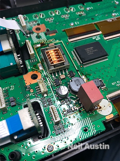
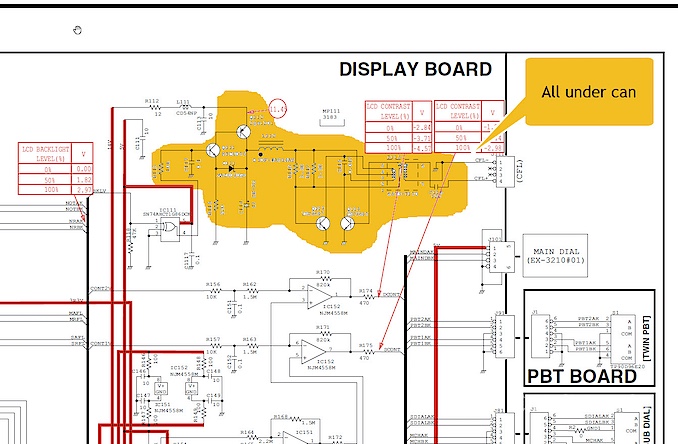
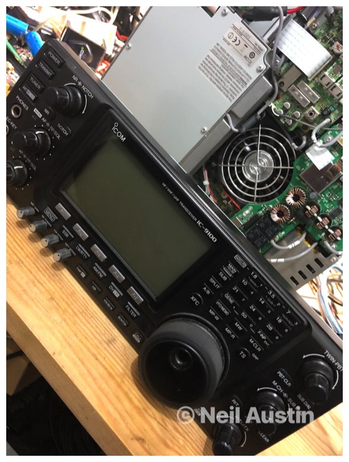
So, a long awaited strip down and repair. The display on the radio is an LCD display backlit by a CFL (compact fluorescent light). The tube went out after it had been working for about 1 hour one evening. Whilst I've got this thing stripped down I'm going to modify the diode matrix to expand the transmit / receive and give me a repeater function.
Let's investigate….

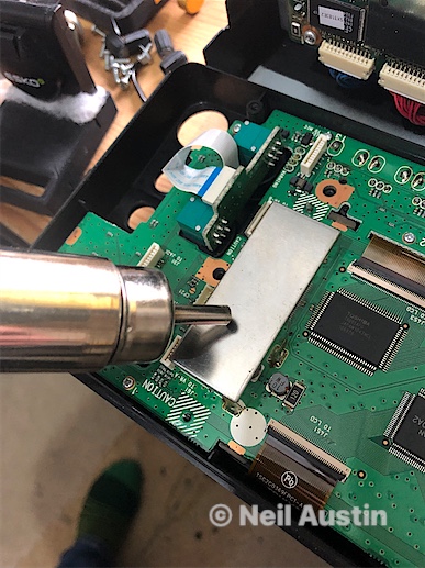
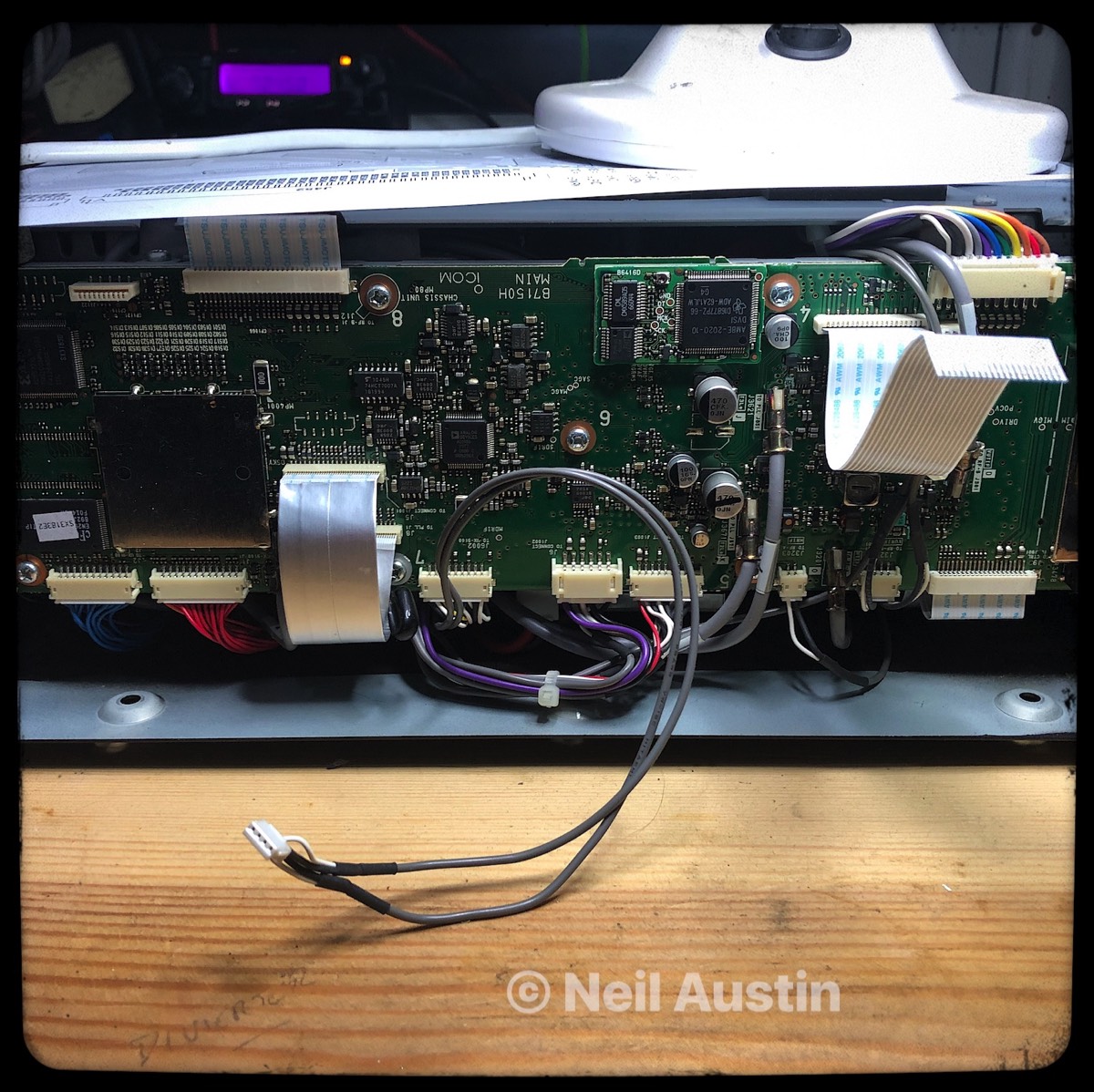
First I took off the covers top and bottom. Removed some side screws attaching the display to the front (2 each side, Countersunk). Disconnected 1 ribbon cable running from the main radio and 2 flexible cables which go to a single connector.
The radio is detached from the front panel so I can get a clearer view to how i can diagnose the problem.

Stacks Image 32
Front unit detached (above)

The top image on the right, shows the ribbon and flexible cable from the main unit which connects to the front panel

The ribbon cable supplies all the voltages which power the head and display on the front of the unit. Check voltages, 5v, -12v, 14v and 8v.
In my case, all voltages we're present give or take. The 14v line was a little low, this supplies the main voltage to power the CFL Oscillator to produce the 80v or so the CFL will need. I don't think at this stage there's anything to worry about as I have run the radio on 12v instead of 13.8v before.

The bottom image on the right shows the dissembled panel under the microscope ready for diagnosis.
Stacks Image 45
Stacks Image 47

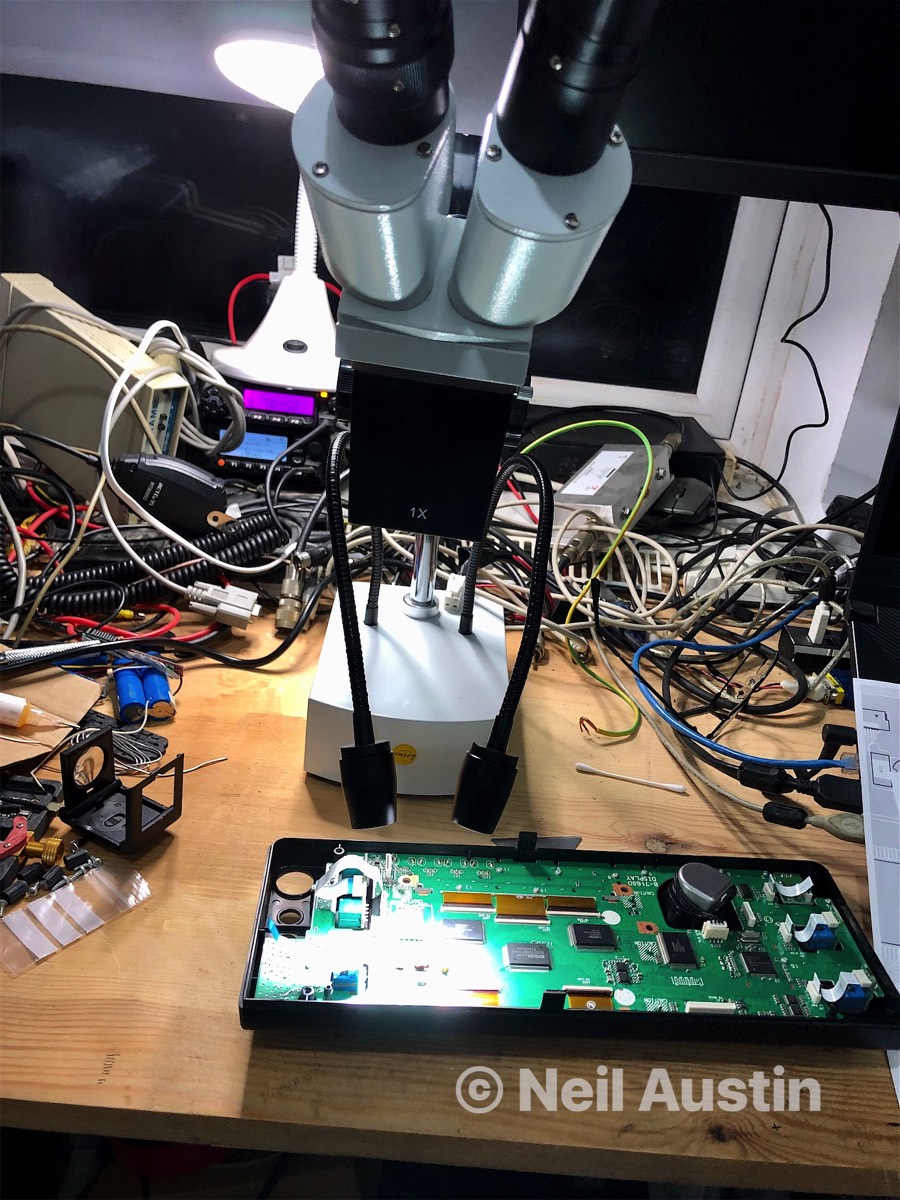
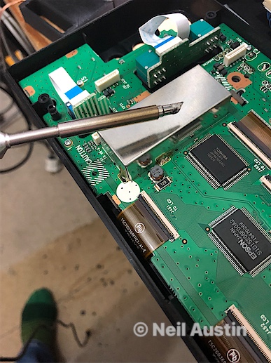
I already had a copy of the Icom IC-9100 service manual so it was down to look in there to strip off some more hardware covering the Display PCB.
Removing tons of screws around the PCB i then took out the 8 pin connector from the front of display turning the fixing ring carefully so not to damage anything. Im sure there may be a tool I could buy or make but at this stage, I continued to ploughed ahead. Something to think about soon when I re-assemble no doubt.

Stacks Image 53
Stacks Image 55
Stacks Image 57
The photo's above show the CFL cover removal from left to right. The circuit is covered to suppress the noise from the oscillating circuit which switches the primary side of the transformer visible on the last photo. I used hot air and a soldering iron with wick to absorb the solder. Keeping the cover up to temperature it came off with pliers no problem.
Stacks Image 61
Here is the circuit diagram of the CFL. The actual problem was the main switching transistor (where it says 11.4) but I opted to re-new the 25uf cap as well because of its age.
I tested the display by connecting only the flexy cable and verifying it worked, I re-assembled the panel and its been fine since. I also tested for variable brightness which worked fine too.